In the first article, we gave an overview of Hailo’s power measurement solution. In the second article, we attempted to reproduce these power measurements with the ElmorLabs solution.
Series: Edge AI Power Benchmarking
In this article, we repeat the same experiment, this time by prototyping a custom INA circuit with available components from Adafruit.
Essential Components from Adafruit
After further investigation, I discovered that Adafruit has several flavors of INA circuit boards, in addition to a USB to I2C board. These components interoperate together to offer a working power measurement solution out of the box.
- Adafruit FT232H Breakout - General Purpose USB to I2C - $15 USD
- Adafruit INA228 I2C Power Monitor - $14 USD
- STEMMA QT / Qwiic JST SH 4-pin Cable - $1 USD

We will be combining this with the ElmorLabs PCIe power insertion adapter, which exposes the 3V3 rail as a jumper, which we can easily tap into.
Assembling the System
This solution was significantly easier to set up.
The FT232H breakout had a single switch to set for use with I2C:
- I2C Mode : set to ON
Regarding the INA228 module, contrary to what I was expecting, no soldering was required to configure the board. The FT232H breakout and INA228 module were connected with a STEMMA QT cable.
I adapted a 2 wire power cable I had, and exposed one of the ends to connect up to the INA228 module. I also wired the +V terminal to the Vbus, for use in High-Side mode (i.e. measuring the 3.3V rail, instead of ground)
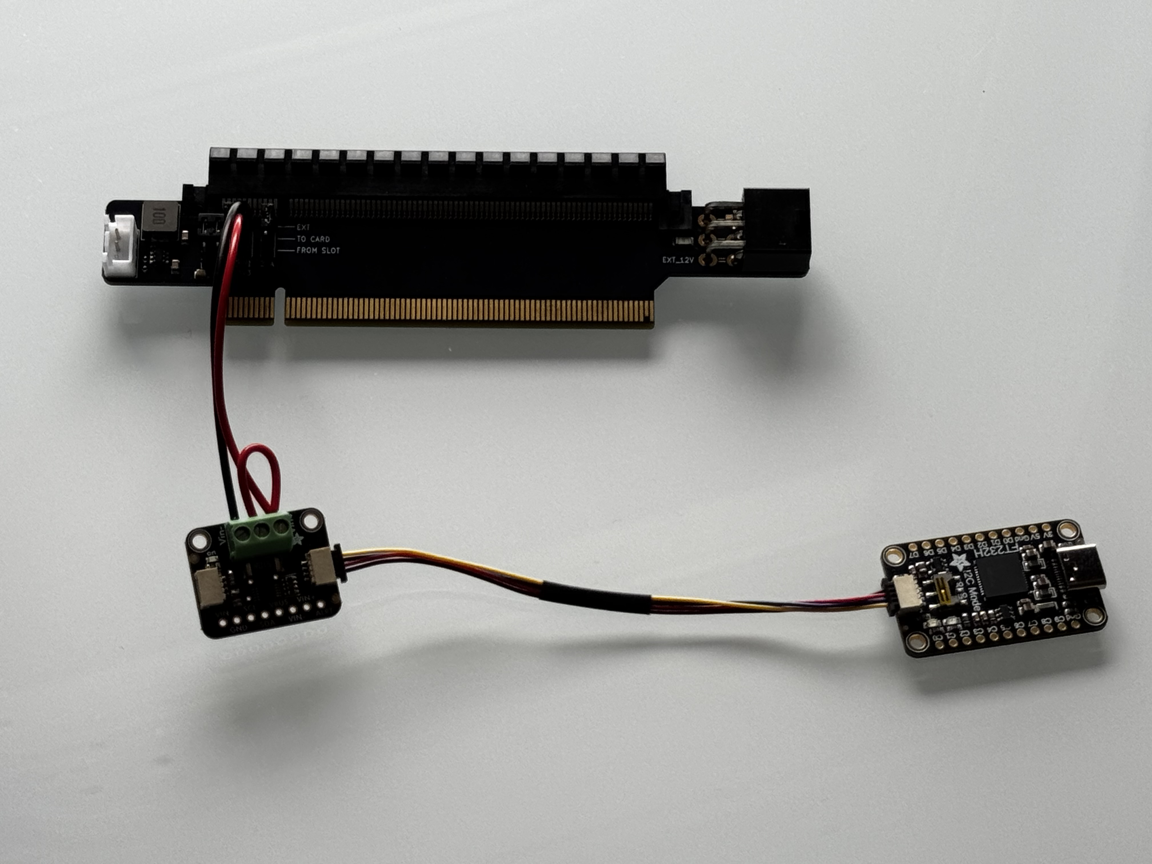
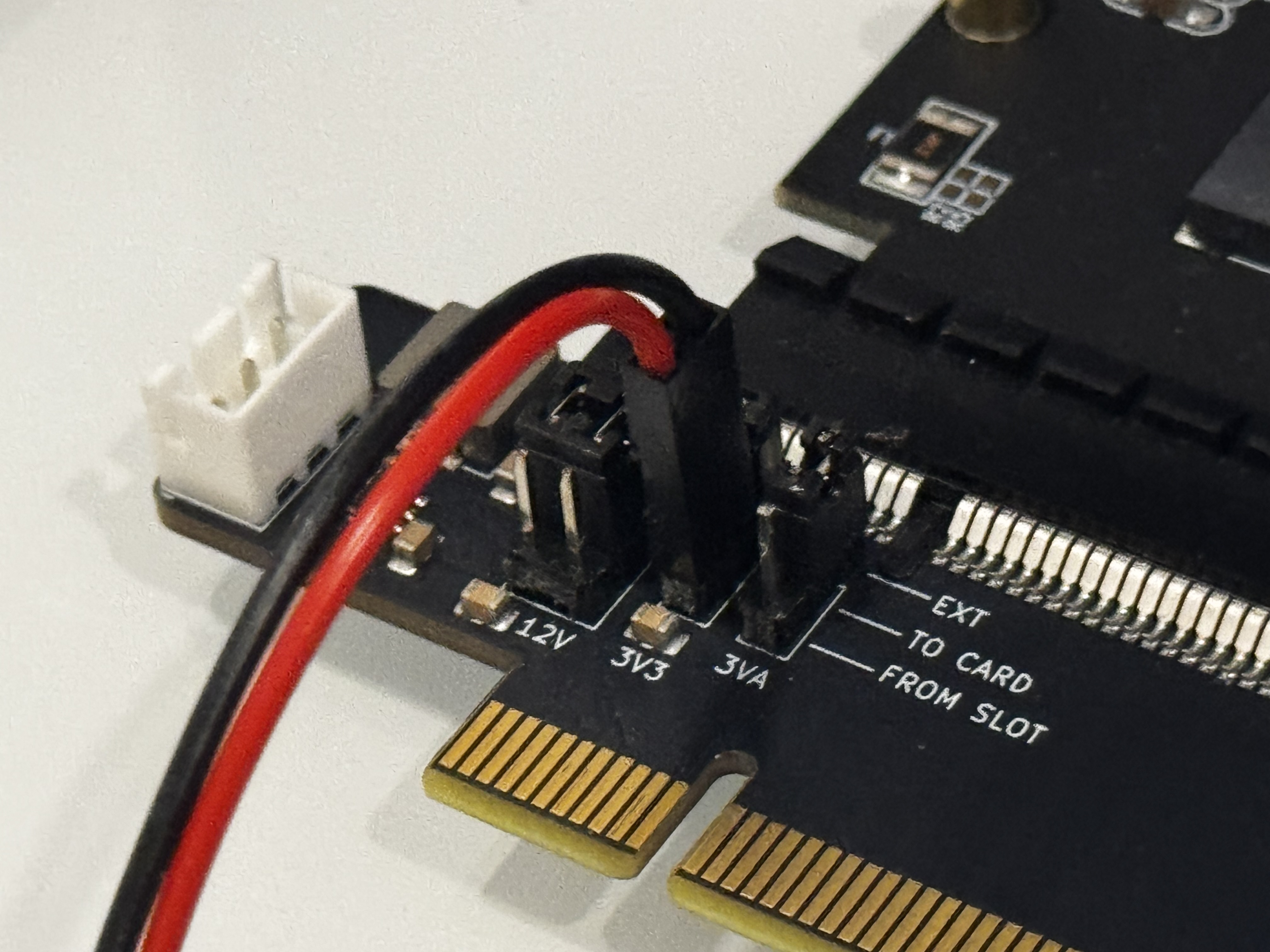
My custom cable was inserted on the jumper site of the 3V3 rail on the ElmorLabs PMD power insertion adapter. In order to get positive readings, the important connections to make are:
- V+ connected to 3V3 (red cable) - (FROM SLOT) pin
- V- connected to 3V3 (black cable) - (TO CARD) pin
Measuring Hailo-8 Power with mb-powermon.py
In order to perform our testing, I have added support for the Adafruit FT232H and INA228 components in my mb-powermon.py utility
The first step is to clone the repo for my open-source power monitoring utility.
(hailo_virtualenv) $ git clone https://github.com/AlbertaBeef/mb-powermon

(hailo_virtualenv) $ cd mb-powermon
Within the hailo docker container, install the “pyftdi”, “adafruit-blinka”, and “adafruit-circuitpython-ina228” python packages.
(hailo_virtualenv) $ pip3 install pyftdi adafruit-blinka adafruit-circuitpython-ina228
Make certain you have permission to access the enumerated FTDI USB device. I have included a script that can be run outside the docker container called fix-ft232h-permissions.sh (use with caution):
$ ./fix-ft232h-permissions.sh
[ft232h-fix] scanning /sys/bus/usb/devices for VID:PID 0403:6014...
[ft232h-fix] found FT232H at sysfs path /sys/bus/usb/devices/9-1/ (bus=9 dev=2)
[ft232h-fix] device node: /dev/bus/usb/009/002
[ft232h-fix] current permissions:
crw-rw-r-- 1 root root 189, 1025 May  5 02:48 /dev/bus/usb/009/002
[ft232h-fix] current mode is 664 (need 666 for non-root pyftdi access)
[ft232h-fix] udev rule already present in /etc/udev/rules.d/11-ftdi.rules
[ft232h-fix] reloading udev rules and re-triggering...
[sudo] password for abbeefai:
[ft232h-fix] permissions after reload:
crw-rw-rw- 1 root root 189, 1025 May  5 02:54 /dev/bus/usb/009/002
[ft232h-fix] SUCCESS — mode is now 0666.
[ft232h-fix] next: restart your docker container so the new permission is visible inside.
Next, inside the Hailo docker container, we can launch the mb-powermon utility as follows:
(hailo_virtualenv) $ python3 mb-powermon.py --probe hailo,adafruit --csv mb-powermon-hailo-ina228-resnet50-20260504.csv
If we re-run the hailortcli utility in a separate console within the Hailo docker container:
(hailo_virtualenv) $ hailortcli benchmark resnet_v1_50.hef
Starting Measurements...
Measuring FPS in HW-only mode
Network resnet_v1_50/resnet_v1_50: 100% | 20577 | FPS: 1371.25 | ETA: 00:00:00
Measuring FPS (and Power on supported platforms) in streaming mode
[HailoRT] [warning] Using the overcurrent protection dvm for power measurement will disable the overcurrent protection.
If only taking one measurement, the protection will resume automatically.
If doing continuous measurement, to enable overcurrent protection again you have to stop the power measurement on this dvm.
Network resnet_v1_50/resnet_v1_50: 100% | 20580 | FPS: 1371.46 | ETA: 00:00:00
Measuring HW Latency
Network resnet_v1_50/resnet_v1_50: 100% | 4036 | HW Latency: 3.20 ms | ETA: 00:00:00

=======
Summary
=======
FPS     (hw_only)                 = 1371.26
        (streaming)               = 1371.47
Latency (hw)                      = 3.19887 ms
Device 0000:c5:00.0:
  Power in streaming mode (average) = 3.95935 W
                          (max)     = 3.95935 W

(hailo_virtualenv) $ hailortcli benchmark resnet_v1_50.hef
Starting Measurements...
Measuring FPS in HW-only mode
Network resnet_v1_50/resnet_v1_50: 100% | 20577 | FPS: 1371.26 | ETA: 00:00:00
Measuring FPS (and Power on supported platforms) in streaming mode
[HailoRT] [warning] Using the overcurrent protection dvm for power measurement will disable the overcurrent protection.
If only taking one measurement, the protection will resume automatically.
If doing continuous measurement, to enable overcurrent protection again you have to stop the power measurement on this dvm.
Network resnet_v1_50/resnet_v1_50: 100% | 20580 | FPS: 1371.46 | ETA: 00:00:00
Measuring HW Latency
Network resnet_v1_50/resnet_v1_50: 100% | 4232 | HW Latency: 3.15 ms | ETA: 00:00:00

=======
Summary
=======
FPS     (hw_only)                 = 1371.26
        (streaming)               = 1371.48
Latency (hw)                      = 3.14771 ms
Device 0000:c5:00.0:
  Power in streaming mode (average) = 4.02821 W
                          (max)     = 4.02821 W
NOTE: You may notice that hailortcli is reporting identical average and max values (e.g., 3.95935 == 3.95935, 4.02821 == 4.02821). As explained in Part 1, this is a signature of contention when two applications read the Hailo power API simultaneously — which is exactly what’s happening here, since mb-powermon.py is also polling the API for comparison. I recommended against this in Part 1, and I’m doing it deliberately here only to overlay both measurements on the same plot. The Hailo values shown should be treated as approximate references, not ground truth. For a clean Hailo reading, run hailortcli alone, as in Part 1.
While this is running, you will see something similar to the following (video playing at 10x speed):
In this video, I am benchmarking resnet50 twice on the same Hailo module.
If we convert the output .csv file to a user-friendly .html, we can plot power and temperature for both runs and overlay Hailo’s reported averages:
(hailo_virtualenv) $ python3 csv-to-html-plot.py --input mb-powermon-hailo-ina228-resnet50-20260504.csv --output mb-powermon-hailo-ina228-resnet50-20260504.html
The first thing that jumps out with these results is that the INA228 measurements are slightly higher than Hailo’s own measurements.
This is the expected behavior. Each shunt resistor drops a small voltage across itself, leaving the load downstream with slightly less supply voltage. Since P = V · I, the load consumes slightly less power, and any downstream sense resistor reads correspondingly lower. The INA228 sits upstream of Hailo’s internal shunt, which contributes to the readings being higher.
I am very happy with these results!
Conclusion
In this article, we have found a working solution to measure power for M.2 AI accelerator modules.
At a total price of ~$60 (FT232H + INA228 + cable + ElmorLabs PCIe adapter), the Adafruit solution is a cost-effective solution. One improvement could be a casing to encapsulate the FT232H and INA228 boards.
With a validated power measurement methodology, we can now compute the metric that matters for edge AI: FPS per watt.
On resnet50, the Hailo-8 delivers ~1371 FPS at ~4.0 W — roughly 343 FPS/W.
This figure becomes our first reference point against which other M.2 AI accelerators can be measured in future articles, using the same methodology applied here.
Alternate PCIe power insertion adapter
Since this article was published, the ElmorLabs PCIe power insertion adapter, which exposes the 3V3 rail as a jumper, has been out of stock.
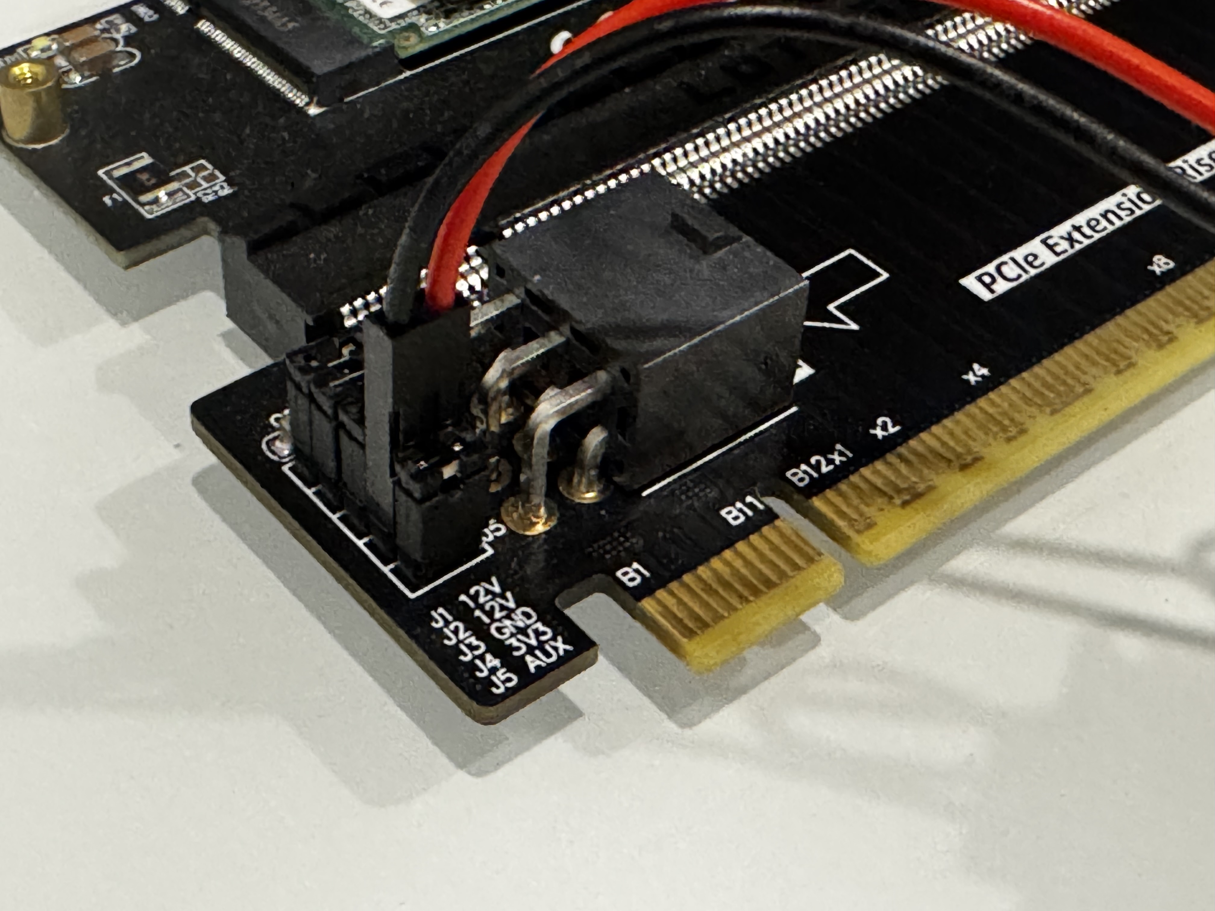
I found another working alternative. The ADTLink R33G PCIe power insertion adapter also exposes the 3V3 rail as a jumper, and also works with the methodology described in this article.
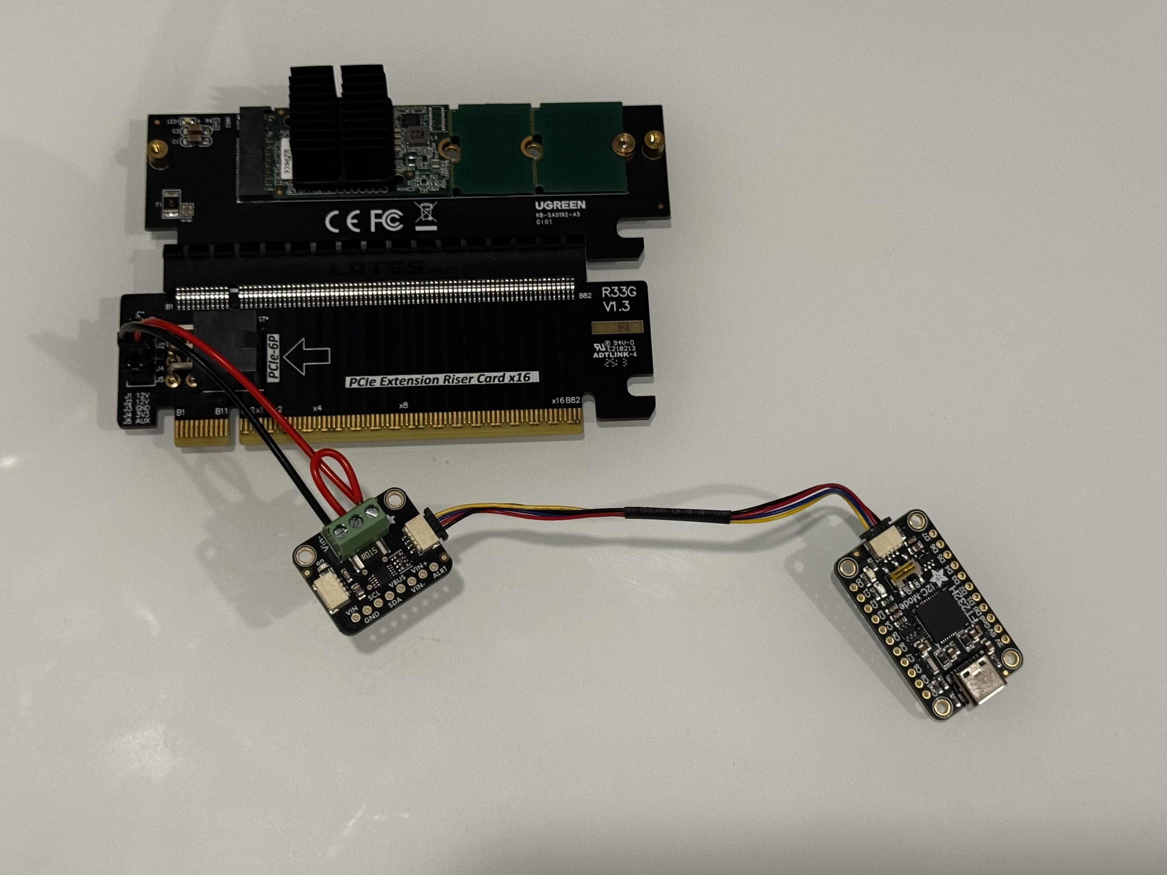
On this PCIe riser, the important connections to make are:
- V+ connected to 3V3 (red cable) - inner pin
- V- connected to 3V3 (black cable) - outside pin
Version History
| Date | Description |
|---|---|
| 2026/05/05 | Initial Draft |
| 2026/06/15 | Document alternate PCIe riser |